About a month ago, I was presenting an idea to make drones faster on race tracks: The so called
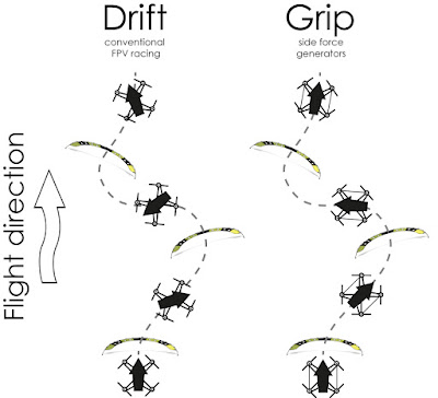
‘side force generators’ (SFGs) enable racing drones to drift less during turns, making them potentially faster. The placement of the ‘wings’ is very critical and mentioned in more detail in my
earlier post on SFGs. Some people tested the SFGs and confirmed the enhanced flight characteristics. Other people didn’t try and didn’t believe that SFGs could help. I must agree that the concept of the SFGs is not so easy to understand. That is why I will explain it in more detail here.
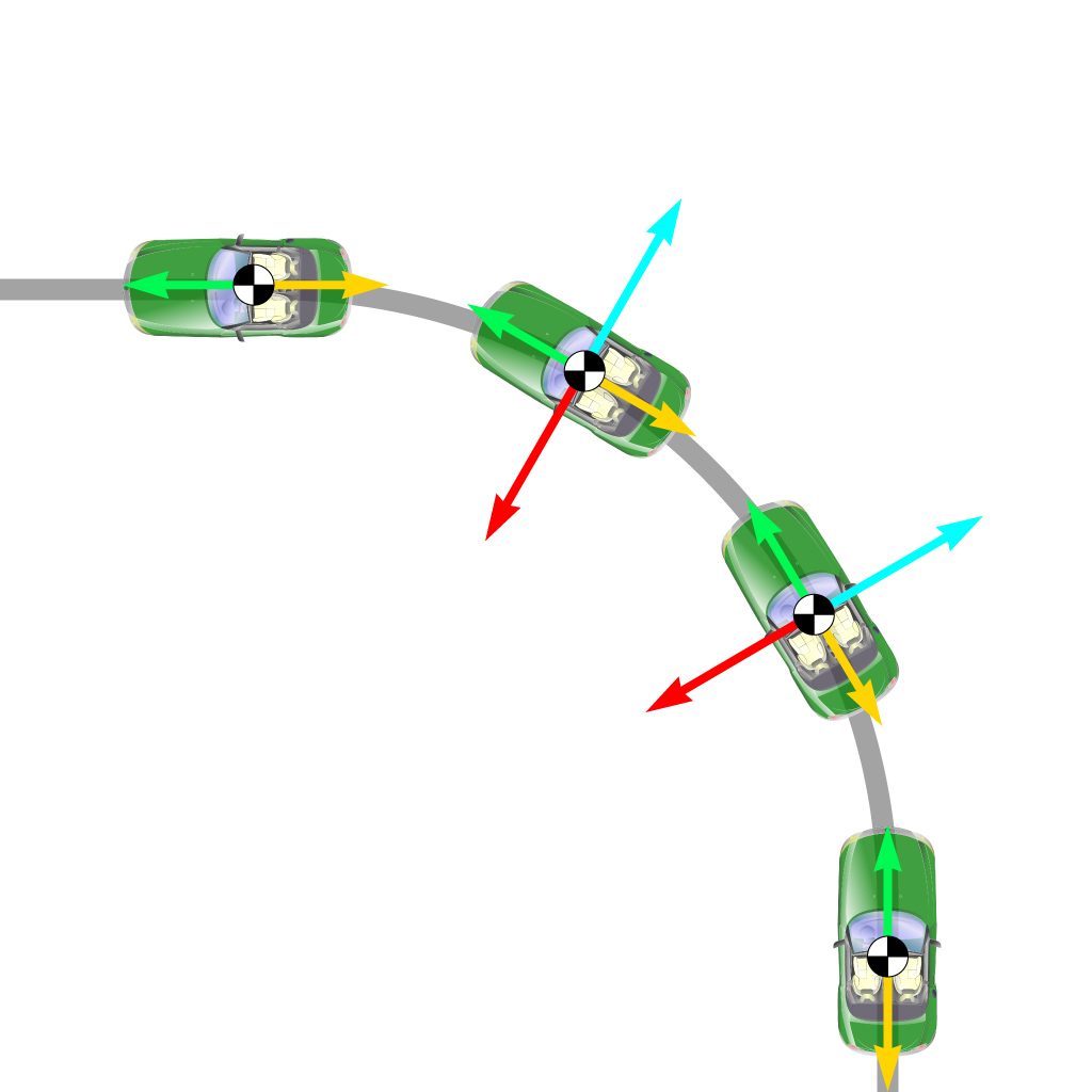
Let’s start with something that everyone knows (figure 1). When you are going through a fast turn with your car, then your car needs to provide two forces to stay on the track (grey line): The ‘thrust’ (green) of your car needs to equal its aerodynamic and friction drag (yellow). When the car turns, then there needs to be a constant force towards the centre of the turn, called
‘centripetal force’ (red). This force is always required to make bodies follow a curved path.
 |
| Figure 1: A car during a turn (top view) |
It is calculated as: Fcentripetal = mass * velocity2 / radius
If it is not present (e.g. when there is ice on the road), then the car cannot follow the curved path, it will continue straight. (The centrifugal force (blue) is a pseudo force, directed away from the axis of rotation. It is not required for the explanation of turning.)
The tyres of a car (figure 2, black arrows) provide the thrust force (via friction) and the centripetal force (via cornering force). You can also get rid of the cornering force of a tyre, then you will be drifting (see animated GIF).
 |
| Drifting (nice, but slow) vs gripping (fast) in RC cars |
 |
| Figure 2: Forces of the tyres (black arrows) |
The centripetal force is a significant force! A standard car (weight = 1500 kg) that drives at 100 km/h and follows a circular path with 16 meters diameter needs 150 kN of centripetal force (that equals 15 tons)!
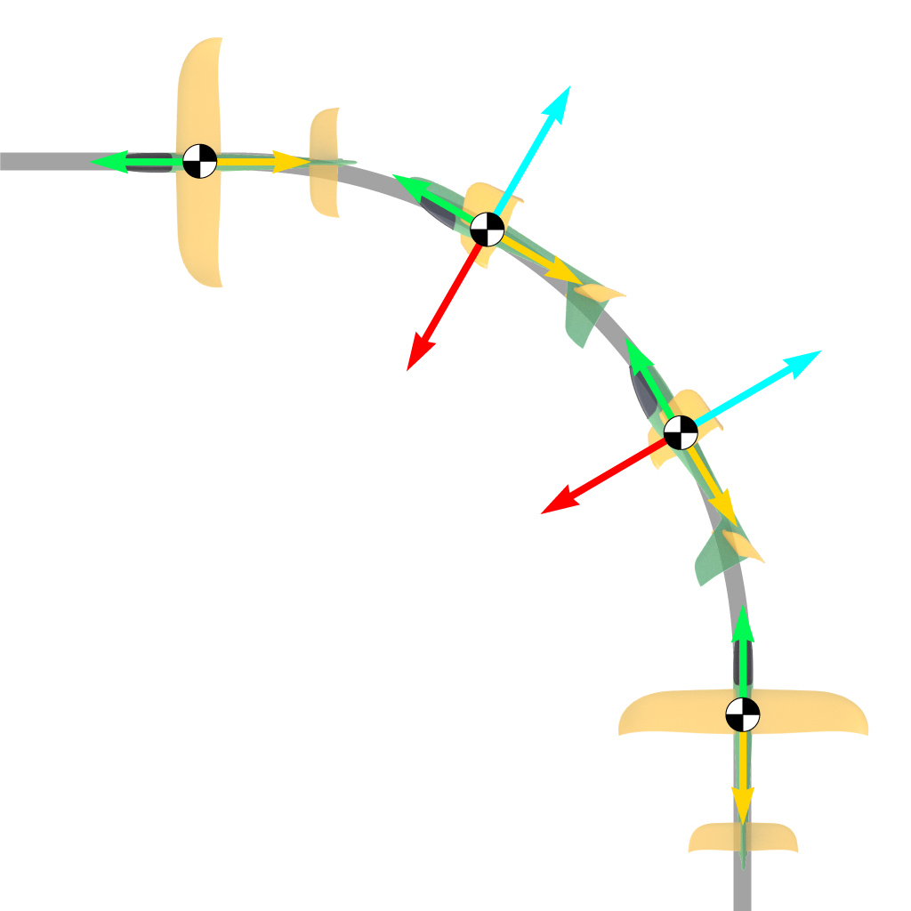
An airplane works like a car when performing a turn (figure 3): Thrust (green) is generated by a propeller, it equals the total drag of the airplane (yellow). During the turn, the airplane rolls left. The wings create the centripetal force (red) via extra lift that is directed towards the centre of the turn. These two forces (thrust and centripetal force) are mostly independent from one another, because they are generated by two different parts of the airplane (propeller and wing).
 |
| Figure 3: A fixed wing plane during a turn (top view) |
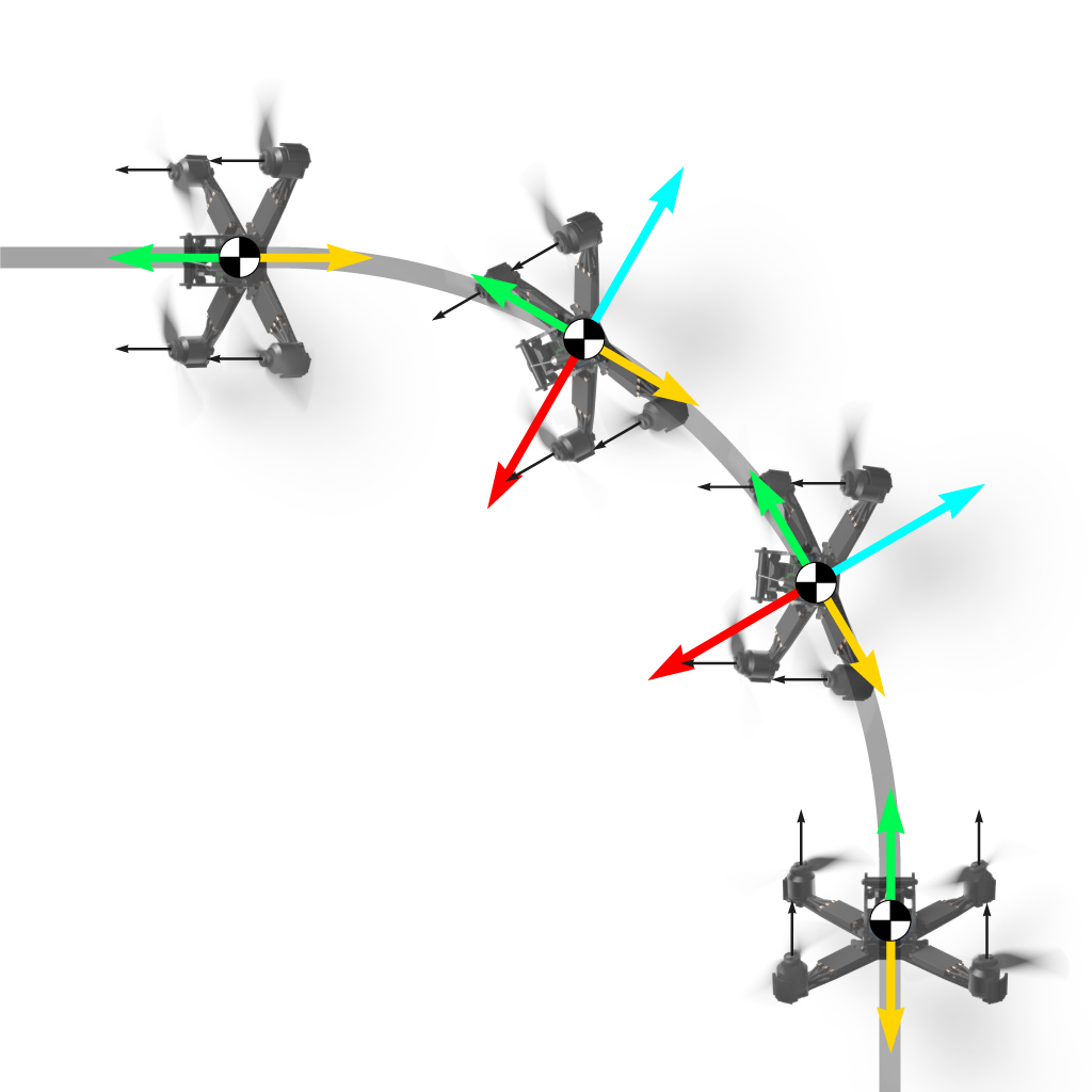
This is very different in multirotors. They do not have wings, therefore all forces during a turn need to be produced by the propellers. The only way to make a turn and to create sufficient centripetal force (red) is to rotate your nose towards the centre of the turn. This will redirect the forces of each propeller (black), resulting in sufficient centripetal force (red).
 |
| Figure 4: A copter during a turn (top view) |
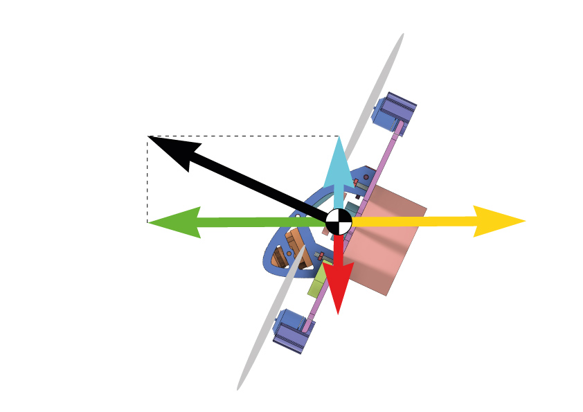
But redirecting the force is not the optimal solution as I will show you in the following paragraph. Up to now, we ignored gravity, as it would unnecessarily complicate things. But let us assume that we have a multirotor that is travelling straight and with
full throttle. The pitch angle is about 70 degrees (figure 5).
 |
| Figure 5: A copter in fast flight (side view) |
The total force of the propellers (black) constitutes of
- a horizontal ‘thrust’ component (green) that equals the aerodynamic drag of the copter (yellow)
- a vertical ‘lift’ component (blue) that equals the weight of the copter (red)
The copter now wants to start a turn. We have learned, that the copter needs to create a significant centripetal force for turning to stay on the grey path.
But the motors already run at full throttle, there is no way to generate additional centripetal force! As the weight of the copter is constant, the only solution to have a ‘force buffer’ for the centripetal force is to reduce the drag of the copter. This can only be done by reducing the speed.
When motors run at full throttle, the only way to have enough motor power to generate sufficient centripetal force is to reduce speed. You need to slow down, which is not what you want during racing (in theory, you could also reduce the weight of a copter by accelerating downwards, but this is not really a practical solution).
But here is the good news: Side force generators offer (almost) free centripetal force for everyone! The key is that they work like wings and provide high lift (per definition perpendicular to the incident flow and hence directed towards the centre of the turn) while they only have a very small amount of extra drag. The ratio of lift and drag (L/D) depends on a lot of things, e.g. Reynolds number, air foil, angle of attack and aspect ratio.
 |
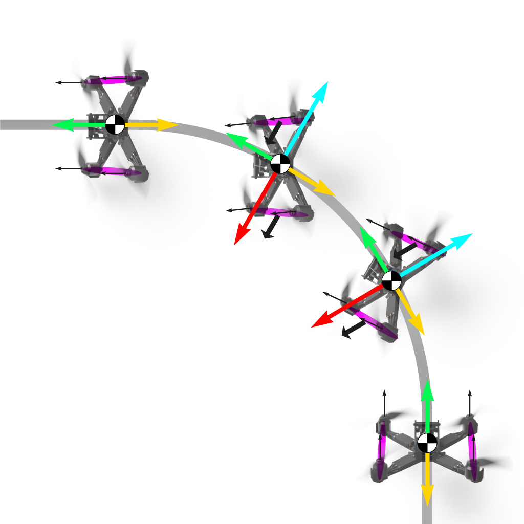
| Figure 6: A copter in a turn equipeed with SFGs (top view) |
The 'wings' create lift (black arrows) towards the centre of the turn. The nose does not need to be directed towards the centre of the turn that much anymore. The propellers do not need to contribute much centripetal force, but can be mainly used to compensate the aerodynamic drag at higher speeds. The copter will fly faster - in theory and in practice.
The SFGs that I use are mounted directly in the propeller jet, that means that they can easily achieve lift coefficients of unity while the drag coefficient stays small. At elevated flight speeds, a centripetal force (= lift) of 500g can be achieved – which equals the take-off weight of standard racing drones.
This centripetal force is offered almost for free - don’t miss it!
I hope that this explanation is clear and helps to understand the benefits of SFGs, otherwise please comment and I will adjust the text.


hello , in picture black arrows are in the same way . How it could be if wings are symmetrics (and vertical ? ) ?
ReplyDeletenormaly we should see black arrows in opposite way and with different strentgh which create by difference this centripetal force .
Hi, I don't really get your question, but there will be a third (and last - promised!) part that will cover the air flow around the SFGs (simulation and flow measurements). This should clarify ALL open questions... At least that is my hope ;)
Deletehello , i ve understood maybe im wrong . i first thought that centripetal force coming from this case see picture : http://hpics.li/e57f642
Deletebut in fact you are talking about that : http://hpics.li/100b16e
im right ?
Yes, the second one is more correct! I hope that I'll post the third article this week, it addresses this issue in more detail.
Delete